IMU Calibration
| This documentation was generated with the assistance of AI. Please report any inaccuracies. |
The com.irurueta.navigation.inertial.calibration package (and its accelerometer, gyroscope,
magnetometer, bias, generators, intervals, and noise sub-packages) estimates the systematic
errors of an accelerometer, gyroscope, and/or magnetometer — bias, scale factor, and cross-axis coupling
— and, once known, corrects ("fixes") raw sensor readings back to their true values.
This package is by far the largest in the library (around 280 classes). Rather than one page per class, this documentation groups classes by what they do, since the vast majority of classes are boilerplate variants (different robust outlier-rejection strategies, different measurement orderings, unit conversions) of a much smaller number of distinct algorithms.
The sensor error model
Every calibratable sensor in this library (accelerometer, gyroscope, magnetometer) is assumed to follow the same linear error model: a fixed bias, plus a matrix of scale-factor and cross-coupling errors applied to the true signal, plus noise. For the accelerometer:
The gyroscope additionally picks up a g-dependent bias driven by the specific force sensed by the accelerometer (typically caused by mass unbalance in the spinning/vibrating element):
and the magnetometer follows the accelerometer’s form, with "hard iron" playing the role of bias and "soft iron" playing the role of cross-coupling:
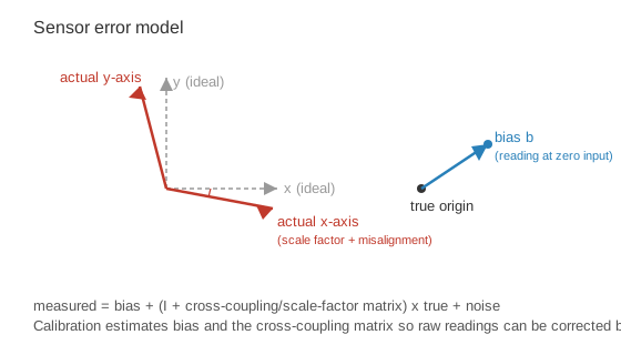
Calibration means estimating and (and, for the gyroscope, ) from measurements taken at known or partially-known references. Fixing means applying the inverse of this model to a raw reading once those parameters are known, to recover (see Fixers: Undoing the Sensor Error Model).
, , and
above are always resolved about body-frame axes — the raw sensor
reading itself is never "in NED." NED only appears as one of two interchangeable ways to describe the
known frame/position some calibrators need alongside a measurement: FrameBodyKinematics (see
Calibration Data Model) stores that frame internally as ECEFFrame and exposes an
NED-converted view via getNedFrame()/setNedFrame(), and calibrator families such as
KnownPositionAccelerometerCalibrator (Accelerometer Calibration) and
TurntableGyroscopeCalibrator (Gyroscope Calibration) accept a position as either
NEDPosition or ECEFPosition — neither is mandatory. Only the magnetometer’s WMM-position families
(Magnetometer Calibration) and the bias estimators
require geodetic (NED-style latitude/longitude/height) position, since that is what
the WMM and gravity models are keyed on.
|
|
Do not confuse the point above (the resolving frame for a known position, which is flexible) with the
body-frame axis convention of , ,
and themselves, which is not flexible: every equation and every
|
Map of the package
| Page | Covers |
|---|---|
Data containers shared by every calibrator: triads, |
|
|
|
The |
|
The |
|
The |
|
Static/Dynamic Interval Detection and Measurement Generation |
Static/dynamic interval detection and measurement-sequence generation — the preprocessing step before calibration. |
Noise (PSD/root-PSD) and approximate-bias estimators used to seed calibrators and Kalman filter configs. |
Why so many classes per algorithm?
Every non-trivial calibration algorithm in accelerometer, gyroscope, and magnetometer appears in up
to six forms:
The base (non-robust) calibrator is the one that actually implements the algorithm’s math — it assumes
every input measurement can be trusted. The five Robust* classes wrap it with an outlier-rejection
strategy from `irurueta-numerical-computing’s robust-estimator framework, useful when some measurements
(e.g. from a noisy or disturbed static interval) might be bad. This documentation describes each
algorithm’s math once and lists all six forms in a summary table, rather than repeating the same
equations six times.
Where to go next
-
Calibration Data Model — start here for the shared data types.
-
reference.adoc#bibliography — bibliography, including the Tedaldi et al. paper used by the gyroscope’s "Easy" calibrator.